
Design optimization of micro-heater for the application of TEM
With increasing number projects involving collaboration between different branches, multiphysics modelling has ever increasing demand. Course of "Multiphysics Modelling Using COMSOL" was focused on modelling using COMSOL software. Main focus of the course is to learn multiphysics in conjunction with COMSOL, which is the finite element analysis software and uses different physical models for solving the multiphysics problem.
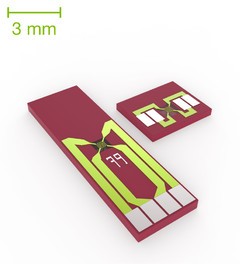
To learn the multiphysics modelling using COMSOL, I chose the project titled "design optimization of the MEMS based heater". MEMS based heater is used in the Transmission Electron Microscopy (TEM) application to analyze the transient behavior of the sample material under heat application. In doing so heater is facing the problem of bulging and thus it is not possible to observe material under the same window settings of the TEM. This problem of bulging is tackled in the modelling and it was desired to eliminate or reduce the bulging as much as possible. As joule heating was used for heating the metal (Platinum) coils, analysis was done using the coupling between mechanical, thermal and electrical domain.
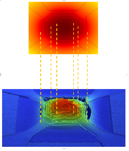
In the following figure, the bulging in actual experiment and bulging with help of 2D modelling in COMSOL are compared for the original design.
Once it had been verified that the COMSOL model is having a correlation with the actual physical model, different designs of the heater were analyzed using COMSOL simulations. All the designed configurations were double spiral and "four probe measurement" scheme (for voltage and current) was used.
For comparison of different designs two criteria were selected.
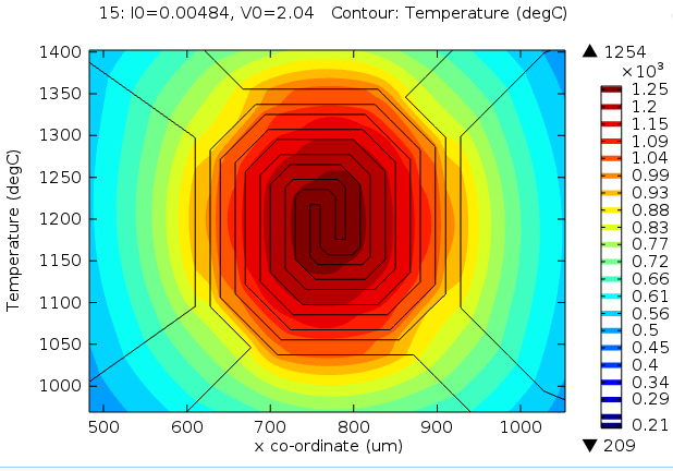
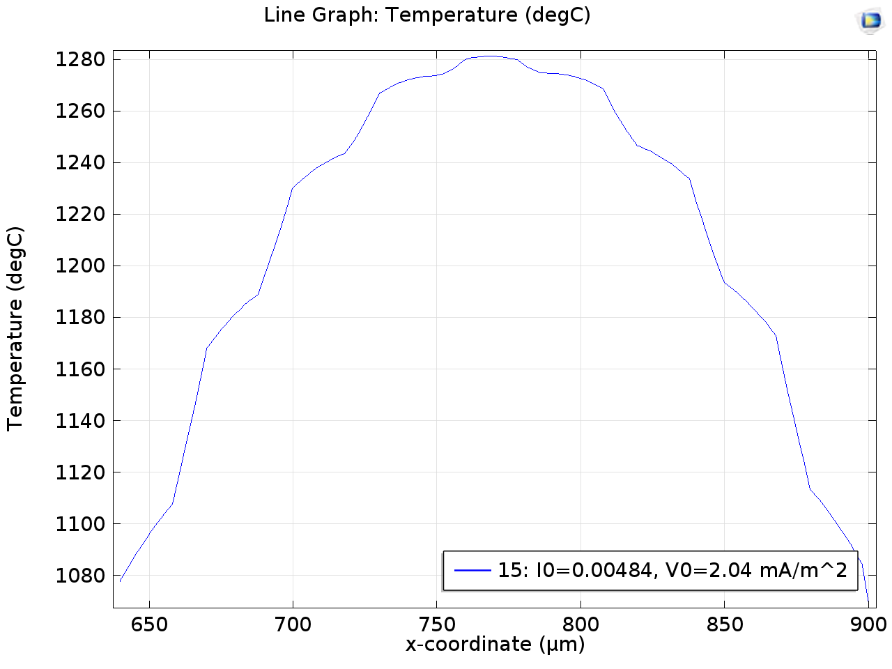
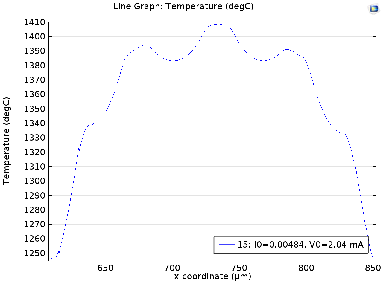
1. Isothermal Contours: It is desired to have as much uniform temperature as possible over the heater lines, thus the design which gives higher area under same temperature is more suitable for the TEM application. In the figures below comparison is done for different designs with the original design.
- Original Design:
- Circular Design:
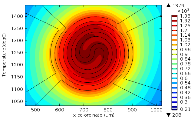
- Rounded Edges:
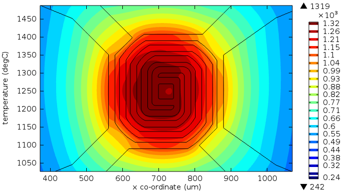
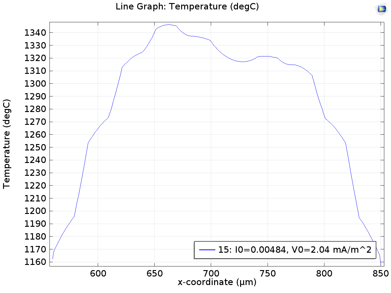
From the figures it is clear that both, circular and rounded edges, design give better isothermal contours and have a wider area having the same temperature than the original design.
2. Current Density
It is evident that where current density is higher, temperature will also be higher, proportionally squared. Thus, it is desirable to have as uniform current density as possible to have the uniform temperature distribution. Again plots of current density are compared hereunder:
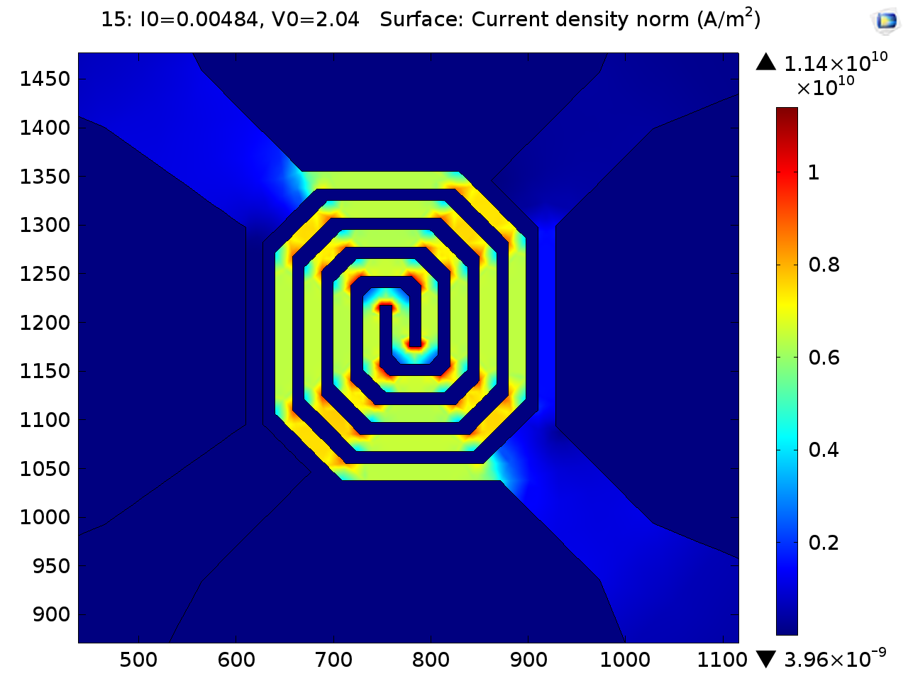
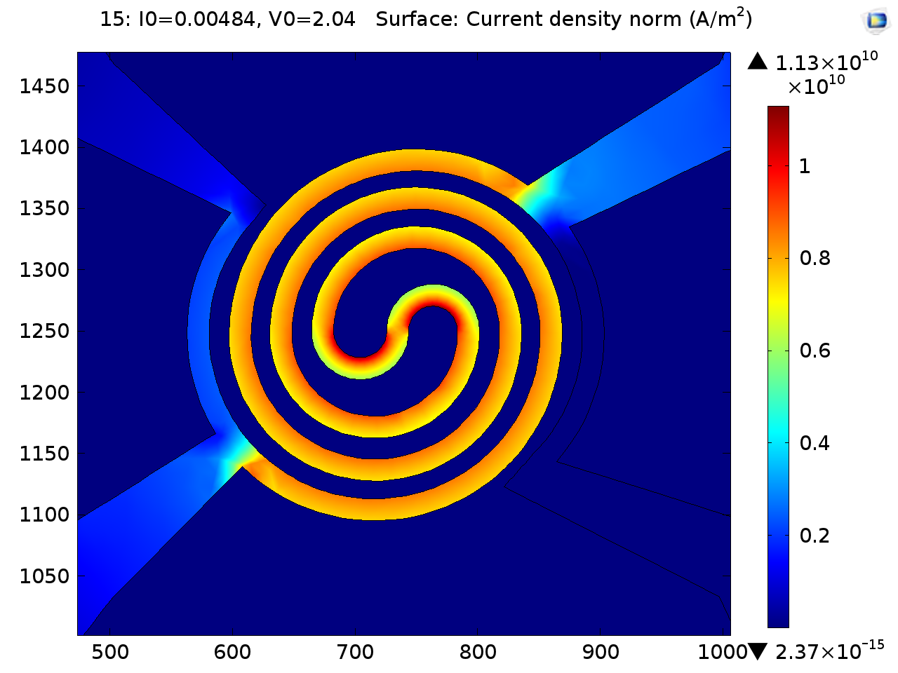
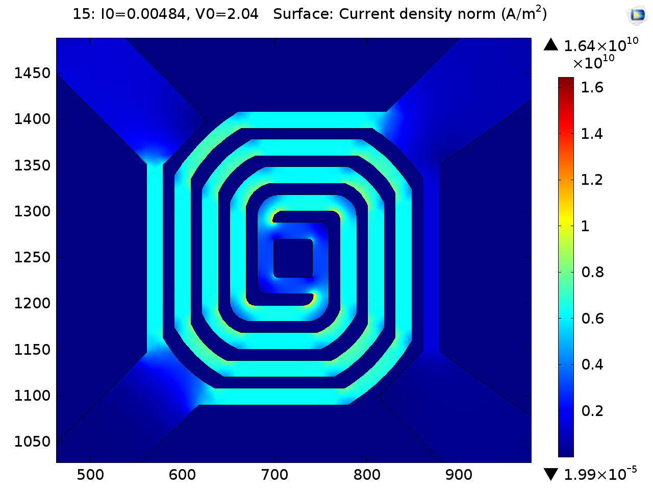
From the plots it can be seen that circular and rounded edges designs give better result than the original one. When looked in detail, it can also be observed that circular design has much more uniform distribution of current density and if the thickness of the metal line would be optimized, circular design will proved to be the best design.
At the end both circular and rounded edges design was given for fabrication and experimentally both designs will be compared.
Learnings and Difficulties:
- During modelling, dimensionality created a major problem for the meshing and COMSOL, along with my system, crashed several times. This led me to simplify the original design and also to reduce the one dimension to make it a 2D design.
- Many aspects of COMSOL multiphysics were not known to me prior to the course, most of them I learned during the course and the project.
- Modelling was done in Solidworks and then imported to the COMSOL. This led me to learn the live link between COMSOL and Solidworks, along with the major learning in import module of the COMSOL.
- As this project was related to the industry, I got to know how the hi-tech industries work on the broader aspect.